7. Build a circuit
Simple LED circuit
Whatever it is, the way you tell your story online can make all the difference.
LED Circuit
Oscillator circuit - part 1
Oscillating
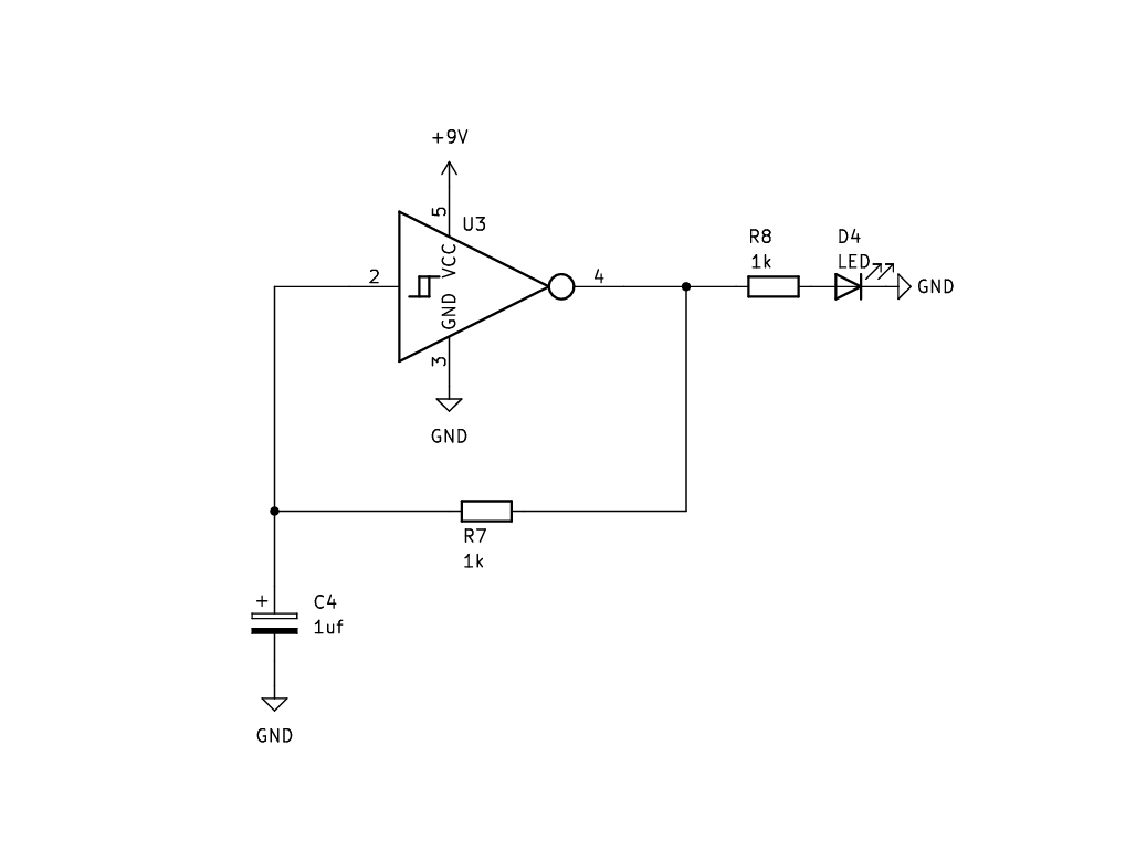
Here we are making a simple square wave oscillator with a fixed frequency. The frequency is defined by the value of the capacitor and the resistor.
We also have an LED on the output so that we can see the square wave output visibly. We will connect to a speaker later.
Oscillator - Part 1
Schematic
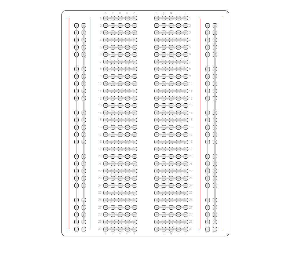
Breadboard
Oscillator circuit explained
An invertor’s function is to output the inverse of its input.
If its input is high then its output will be low.
If its input is low then its output will be high.
When we say low we mean GND, or 0v.
When we say high we mean the invertors positive voltage, so 9v in our case (there may be a threshold somewhere between 0-9v in reality).
So if the input is 0v then the output will be 9v and if the input is 9v the output will be 0v.
Making it oscillate
So if we were to connect the invertor’s output back to its input, it would oscillate very fast from low to high as the output will change the input, which will in turn change the output etc. This is called a feedback loop.
The problem with this is that it would be oscillating incredible fast and in an uncontrollable way. So what we need to do is delay the time between the output changing it value, and the input receiving it. Then as the output changed it would hold for a set time, and then trigger the input, rather than just doing it as fast as possible.
If we change the amount of delay between the output and the input, we will change the frequency of the oscillation.
How do we create the delay?
The way we do this in the circuit is by adding a resistor and a capacitor into the feedback loop.
The resistor will limit the amount of current that can flow between the output and the input.
The capacitor will take time to fill up before allowing current to flow to the input.
Its the combination of these tow components that create the delay. Changing the values of each component individually will affect delay time between the input and output.
Explaining the circuit with the water analogy
Here is a representation of how this circuit would look if we were using the water analogy.
The output of the invertor would be high pressure, pushing water out.
When it gets to the
Oscillator circuit - part 2
Potentiometers
Now we want to figure out how to make the frequency variable.
To do this we either need to add a component that varies the capacitor value or the resistor value.
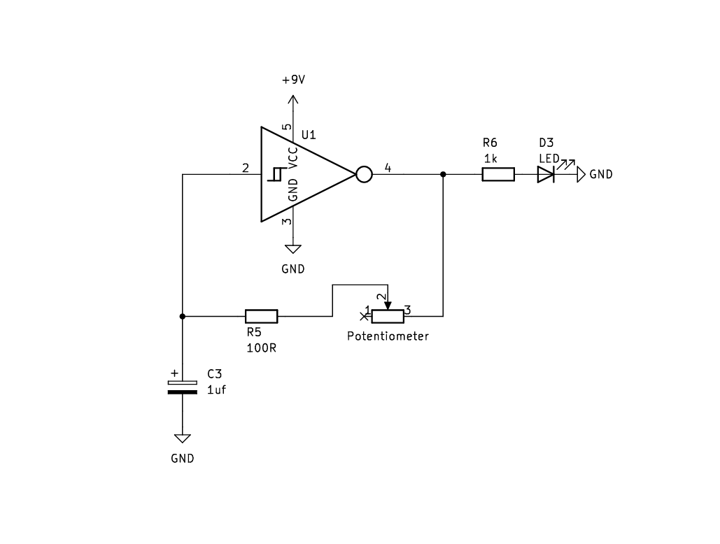
Variable resistors (or potentiometers) are generally what are used for the knobs on a synthesizer. So we need to swap the fixed 1k resistor for a potentiometer to allow us to control the resistance value, ad thus the frequency of the oscillator.
When a potentiometer is fully off it can have essentially 0 resistance, so we need to add in the 100ohm resistor to make sure we don’t short the output to the input.
Oscillator - Part 2
Oscillator circuit - part 3
Light dependent resistors
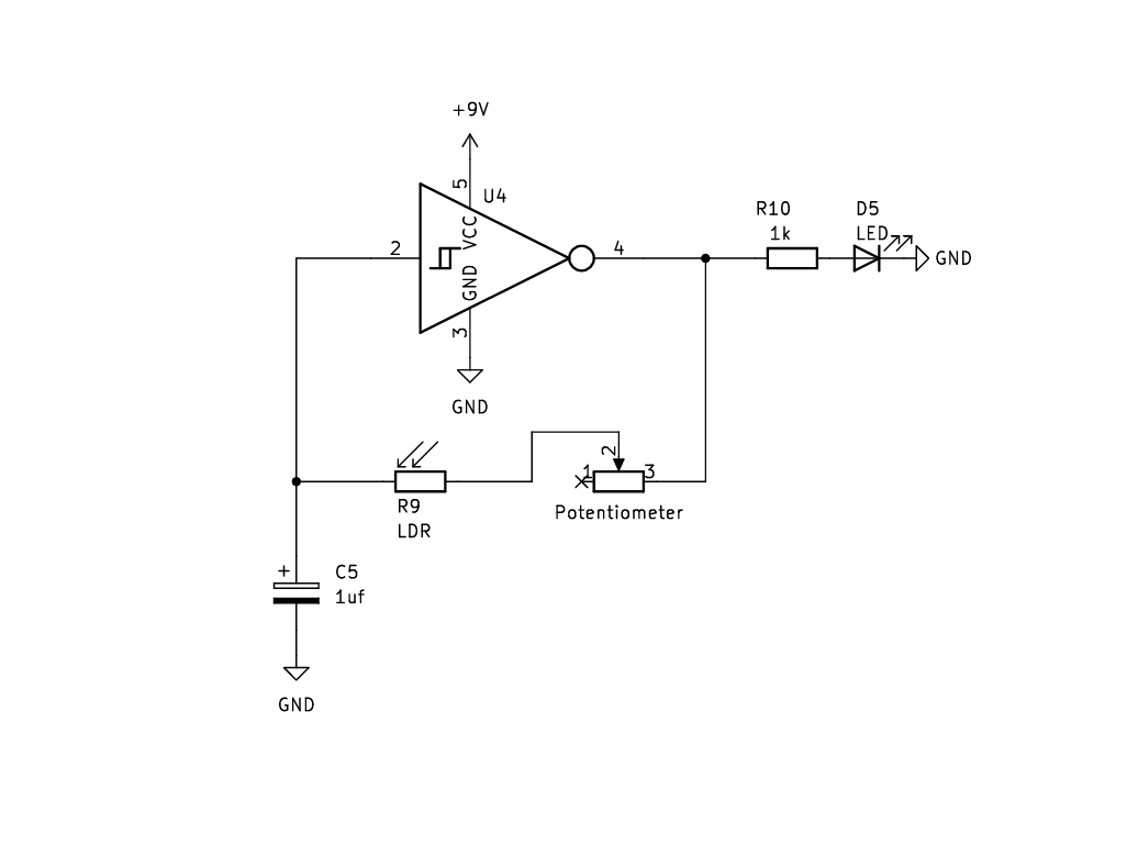
Another way of varying the resistance is to use an LDR.
An LDR (or light dependent resistor) changes its value based on how much light is shinning into it. So in a bright space the resistance will be high, and in a dark space the resistance will be low.
You can use your hand to control the amount of light hitting the LDR which will affect its resistance.
To add the LDR we remove the 100 ohm resistor and replace it with the LDR. LDRs will always have some resistance so we don’t have to worry about shorting anymore
Oscillator - Part 3
Oscillator circuit - part 4
Dual oscillators
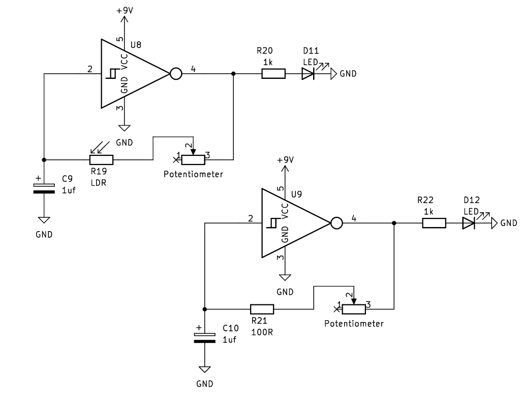
Now we want to make a second oscillator. Remembering that the IC that we are using is a hex invertor, which means it has six invertors, we can simply make the same circuit again using one of the other invertors on the chip.
In the second circuit we will go back to before we added the LDR, so one circuit uses the LDR, and the other has the 100 ohm resistor in its place.
Oscillator - Part 4
Oscillator circuit - part 5
Frequency modulation
Now we have two oscillators we can use one to modulate the others frequency.
Remember that our first oscillator can be controlled by light via the LDR, and both oscillators have LEDs on their outputs, so if we face the LED of the second oscillator into the LDR of the first one, the frequency of the first oscillator will be modulated by the output of the second one.
Using an LED to control an LDR is called a vactrol and can be bought as a component which has both LED and LDR in one package.